The following is a block diagram:
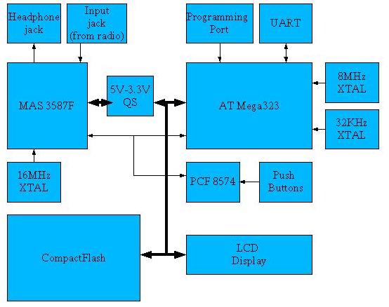
The storage medium chosen was compactFlash. CompactFlash is very useful due to the fact that it has very low power consumption. This is very important for a recording application, where you are not even there to know that the batteries need to be changed.
The main 8 bit data bus is shared by the CPU, LCD display, compactFlash, and MP3 chip. The CPU controls all of the signals to the individual peripherals. In addition, there is am I2C bus between the CPU, PCF8574, and MP3 chip. The PCF8574 is used to read the state of the push buttons. Because I ran out of pins on the AVR, the PCF8574 was a simple and convenient solution to getting the state of the buttons.
There is a programming port for downloading the firmware onto the AVR flash, and an RS232 interface for debug output. The RS232 can also be used to syncronize the Soundwave MP3 with a PC, allowing program information and scheduling information to be downloaded into the Soundwave flash storage.
Several of the ICs were SO packages, which needed an adapter to hook to the 100 pin spacing of the protoype board. The MP3 chip was a PQFP package with 64 pins, which was incredibly hard to mount. The chip distributor send a PCB that converted the PQFP into a more usable SIP package.
The power interface is pretty simple. A 9V AC adapter provides 9V DC, which is then regulated down to 3.3V and 5V with the help of the LM317 regulators. The complete schematic in Adobe acrobat format can be found here.