EE152 Final Project: Battery Charger
Summary
For this project, we decided to implement a battery charger for Panasonic 18650 Lithium Ion batteries. The battery charger we implemented was a constant-current, constant-voltage charger built to charge two batteries in series. This was to serve as a proof of concept for a larger battery pack. This batteries were charged at a constant current at first until the battery reached a threshold voltage, and then were charged at a constant voltage. This ensured that the batteries were being safely charged at acceptable specifications. The entire system is controlled by a Digilent Atlys FPGA which serves as the PID controller for the charger.
To increase the safety and efficiency of the charger, we decided to implement a current recycling method. This is done by bleeding off current from a cell whenever it has more charge than another cell until the charges of the two cells are equal. The simple way of doing this is to use resistors to bleed off current from a cell that needs to lose a bit of charge. The more efficient way is to use a flyback transformer to recycle the charge of the battery. Due to the complexity of this approach we chose to implement the basic current recycling. The flyback recycling was simulated to reflect the operation of a higher performance system.
The basic battery charger that was constructed proved to be successful. Operating at an average efficiency of 94%, it was able to successfully charge the battery at constant current followed by constant voltage. Since charging occurred higher than 1.0 C, the bleed off resistors used proved to be of little value as they could not sink enough current to properly balance the batteries. Specialized control to limit battery charging to 4.2V did allow for safe operation at all times though and balanced the batteries in the long term.
The flyback recycling simulation also proved to be successful and set out a path for future optimization of the battery charger. As the flyback can directly transfer power at varying currents and voltages, the issue of sinking current that appeared in the basic charger is mitigated. Furthermore, the flyback system has the added benefit of increasing the overall efficiency of the system and providing for a greener charging rig. While it may be inconsequential for a small proof of concept battery charger, the small gain in efficiency will have a large impact on a battery pack consisting of several hundred cells. The flyback also provides the benefit of requiring only a single cell voltage control, even for such a large pack, making it safer for regular operation.
Overall, the project served as a good learning experience for the team as we were able to apply our skills to construct a basic test rig while experimenting with a more complex and refined approach to the same problem.
I. Battery Charger Simulation
A. Implementation
The battery charger has four main states of the battery charger: off, constant current, constant voltage, and voltage float. Charger is off (not outputting current) when the battery is at an atypical voltage like 0 or above maximum voltage. Charger is at a constant current mode at first until the battery reaches a threshold voltage. Once it reaches the threshold voltage, the charger will charge at a constant voltage. Finally, the charger will be at a voltage float when the battery is at full charge.
We created Verilog code for our controller and a test-bench program to simulate the state changes in the charger controller in accordance to the voltage and currents sensed by the FPGA.
B. Knowledge Gained
PID controllers are used in a multitude of systems and are key for fine-tuned control of a system. Through this project, we were able to develop a stronger understanding of PID control, especially at the very high frequencies achievable on the Atlys FPGA. We also developed a stronger mastery of Verilog and its associated tools. While we generally used Matlab for simulation, this project gave us an opportunity to experiment with the XISE simulation tools and expand our toolset. We further developed our knowledge of finite state machines and testbenching as it allowed us to easily isolate digital problems from the analog counterparts on the breadboard.
C. Results
The figure below is a matlab graph showing the waveform simulations of the constant current, constant voltage controller. The system is simulated as an RC circuit with a load attached to the end of the output. What we wanted to simulate was the charger initially charging at a constant current if it doesn’t hit the voltage threshold or constant voltage if it does.
From 0 to .005 microseconds, the output load is set very low so that the output current will create a voltage that smaller than the threshold voltage. As seen below, “i out” is brought to steady state at around the CC target and the output voltage has not crossed the voltage threshold. From .005 microseconds onwards, the load is set high so that the output current will create a larger output voltage, meaning the charger must now be in constant voltage mode. As seen below, “v out” is brought steady to CV target.
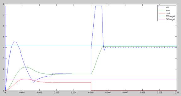
Figure 1: Simulation of Basic Battery Charger
II. Battery Charger
Implementation
A. Implementation
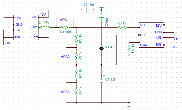
Figure 2: Schematic of Basic Battery Charger
The battery charger uses a standard buck topology with the half bridge module on the left controlling the operation of the buck converter. The Atlys FPGA outputs a PWM on IO0 which controls the output voltage of the buck at the positive pin of ADC1. Depending on the duty cycle, the 10V input is stepped down to the required voltage. The input capacitor is used to reduce the noise seen on the input line.
In order to implement a battery bleeding and charging method, we needed two voltage sensors and one current sensor. ADC0 and ADC3 served as the voltage sensors across the batteries. ADC1 served as the current sensor. In constant current mode, the power converter will be outputting a stable current that it reads from the current sense. In constant voltage mode, the power converter will output a stable voltage for the sum of the two voltages.
The bleed off system was driven by the half-bridge module on the right The low side switch could be controlled very easily since the battery is grounded, but the high side-switch was a bit less intuitive because the switch needed to be biased at a higher voltage. The half-bridge module takes care of the biasing of the high-side switch when it is being used a switching converter, but it cannot be turned on continuously because the bootstrap capacitor that biases it high will fully discharge, making the high-side switch function improperly. Therefore, both switches were operated at 50% duty cycle when the batteries were bled.
The controller we used was the Digilent Atlys FPGA because it had a faster polling frequency, meaning it can do faster control and create a more stable output, which is very important in charging the battery. It measures two voltage values and one current value, and outputs 3 PWM signals (one for buck converter control, two for battery bleed-off control).
B. Knowledge Gained
Buck converters are central to most power electronic systems and this project allowed us to solidify our understanding of buck operation. Since the FPGA required input readings of voltages and current, it also allowed us to build on our knowledge of current and voltage sensing from previous labs. While the current recycling implementation was rudimentary, it forced us to use the half bridge module in a setup that we had not used before, forcing us to get creative. Referencing the datasheets of the half bridge module as well as the FPGA, we were able to develop a workaround that met our needs. Finally, as with any analog system, noise control and attenuation was a concern. Spider grounds, decoupling capacitors, and clean wiring allowed us to keep noise to a minimum.
C. Results
The battery charger successfully charged two batteries in series. The system began in the constant current mode and then transitioned to the constant voltage mode once the batteries had met the voltage threshold. The bleed off system failed to provide great results as charging occurred at a rate greater than 1.0 C. The resistors were unable to sink large amounts of current due to 0.125W power dissipation limitations and low currents failed to discharge the batteries quickly. The use of the FPGA allowed for fine-tuned control, so when a battery reached maximum voltage it held steady while the remaining battery charged up to a comparable voltage. Thus, balancing successfully occurred over longer periods of time (several minutes).
|
Voltage (V) |
Current (A) |
Efficiency |
|
5.8 |
1.07 |
93.3% |
|
7.3 |
1.36 |
94.0% |
|
8.8 |
1.65 |
94.5% |
Table 1: Efficiency of Battery Charger
We also measured the input and output voltages and currents and several operating points to measure the efficiency of the system. They charger averaged a 94% efficiency level which can be improved with flyback power recycling.
III. Battery Charger Power Recycling
A. Implementation
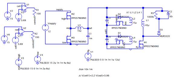
Figure 3: Flyback Recycling Battery Charger Schematic
Considering the fact that we are using a lab power supply (since our strings are made up of only two cells), we needed not consider charging in isolation and, therefore, used a buck converter to set the charging voltage and current. The output of the buck converter was connected to the string and the primary of a flyback converter.
To move charge around cells without wasting power in resistive heating, we used a flyback converter with the primary connected across the charging voltage and a secondary connected across each cell. The secondary is in series with a switch and a diode. The switch is activated when there is a charge imbalance in its respective cell. The diode is to ensure that no current flows around the cell in the other direction, thereby further unbalancing the cells. The switching MOSFET controlling the primary current can see extremely high voltages at its drain due to the inductor’s resistance to a change in current. To relieve the charge from the drain node, a RCD snubber was added to recycle the excess current back to the top of the battery string.
The buck converter is switched at 166kHz and the flyback is switched at 83kHz.
B. Knowledge Gained
Flyback converters can be thought of in multiple ways. One way is that an output voltage is induced on across the secondary from an input voltage on the primary. The other way to think about a flyback converter is as a current buffer. Depending on the amount of inductance and duty cycle, the primary will draw a certain amount of current. This energy is released in the secondary as current that is inversely proportional to the size of the secondary inductance. The sizing of the flyback inductors and the duty cycle control the amount of charge that is delivered every cycle across a cell. This could be adjusted after determining the optimal amount of balancing current considering factors such as lifespan and safety.
We learned to implement snubbers to recycle current from converters so that large voltages do not build up to extreme levels, possibly damaging circuit components. Switching frequencies and duty cycles must be chosen carefully as to avoid very large currents when they are not necessary. The smaller currents make for more predictable transients and a slower, more stable charge of the batteries. The balancing can take several minutes depending on how large the disparity and how much charge one chooses to move per cycle.
C. Results
The buck converter control ended up being quite difficult to implement in analog. The control of the switches for each secondary circuit is not difficult to implement, but it complicates the spice simulation to the point where it can no longer converge. The first thought was that because the opamps used for comparison in the gate drive were ideal, the transient would be too quick for spice to be able to handle. After some modification, it was determined that this was not the problem and the reason for failed convergence with gate control was not discovered. To help the simulation converge, initial conditions were set so that the cells were unbalanced. The switch for the cell that held less charge was held on while the switch for the cell that held more charge was held off. The actual balancing takes long enough that this scenario would be so for a substantial amount of time.
With this simplification, we were able to recycle current back to the top of the cell for recharging once every cycle. Given that the top cell in the string had less charge in the bottom cell, the current through the top cell successfully increased by about 100mA for 1us every cycle (12us). The current through the bottom cell decreased by the same amount, resulting in a different change in charge for each cell that, over time, would cause the cells to balance.
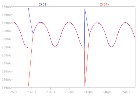
Figure 4: LTSpice Simulation Results