
Figure 1 shows the circuit diagram for the voltage regulator that was built in our system. The input voltage source is a 9 Volt battery. The LM7805 voltage regulator generated a constant 5 Volt DC signal that is used to power up the chip and the rest of the system. The power switch is designed to allow a player to turn on/off the device and preserve battery power.
Figure 1: Circuit Diagram of the Voltage Regulator
A block diagram of the reset switch.Ā The voltage regulator provides the 5 V power supply to the reset switch.Ā When the reset switch is off, the reset output remains as 0 V.Ā When a player turns on the reset switch, the output voltage changes to 5 V.ĀĀĀ
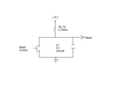
Figure 2: Block Diagram of the Reset Switch
The potentiometer is designed to provide a player a wide range of contrast selections.
The resistors are chosen to match the desired contrast levels of the LCD. The potentiometer can take resistances in the range of 0 <=R <= 9.2 K Ohms. For example, when the player turns the potentiometer to the resistances about 1 K Ohms, the output /input voltage ratio (Pin3/Pin18) would be about 91%. In addition, Figure 3 shows the block diagram of the potentiometer.

Figure 3: Block Diagram of the Potentiometer
The block diagram of the oscillator. The oscillator is selected to qualify the timing requirement of the LCD display. The two terminals of the oscillator are connected to XTAL1 & XTAL2 pins in the microprocessor. With the connection of the oscillator, the microprocessor is adjusted to the 8 MHz oscillator frequency.

Figure 4: Block Diagram of the Oscillator
A block diagram of one push button. When the button is not pressed, the voltage of the output pin stays as 5 V. When the button is pressed, the voltage drops to 0 V. The pull-down resistor is selected to compensate for the flowing voltage that is detected at the output pin and bring the voltage down to precisely 0 V. The resistance value is chosen to be large enough in order to reduce the power dissipation by the resistor.

The interconnections between the Hitachi HD61202 LCD display and the microprocessor. The LCD has 20 pins connections with Pin 19 & 20 as cathode and anode for LED backlight connections. The LCD pins are connected in the following order:

Figure 6: Block Diagram of the LCD Display