Controller Design
For the QRC controller, we decided to go with a PID with a feedforward mechanism to set the duty cycle for the converter. The off time is then calculated based on the output load and the requested duty cycle. However because the control is so dependent on the load, we found that in addition to adjusting the off time calculations, we had to adjust the PID parameters depending on the load as well. We found that if we scaled the parameters down quadratically as we reduced the current draw, we maintained a stable controller.
Results
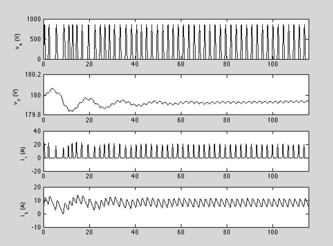
Controller with 22 Ohm load (max load).
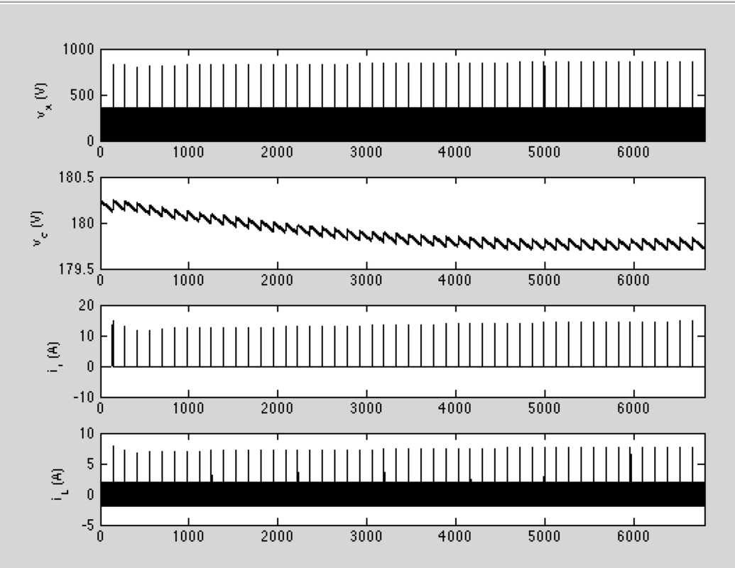
Controller with a 2.2 kOhm load.
Going Forward
There is still further work to be done with this controller. The first of which is to better tune our parameters to achieve the transient response that we want. Additionally we would like to add more complexity to our model for the QRC system so the off time calculation will become more accurate.
There is still further work to be done with this controller. The first of which is to better tune our parameters to achieve the transient response that we want. Additionally we would like to add more complexity to our model for the QRC system so the off time calculation will become more accurate.