
|

|

The figures above show Jakku, all ready to roar!! Our final design ended up taking the form of a towered assembly consisting of three subsystems. First, we have a bottom level which houses our main functionality -- the drivetrain, the tape sensors, the IR sensors and our two battery packs. Second, we have a middle level used as storage for all of our circuits and our Arduino. Finally, we have three upper levels which house our token delivery system and its various components. These levels are held together by 1/4" Threaded Steel Rod and Steel Hex Nuts which run the height of our bot. Not that the majority of the bot is made of laser cut 1/4" and 1/8" duron. For a full list of materials and hardware used, consult the Bill of Materials Section.


|

|
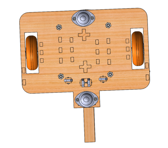
We also created a full CAD model of our design in order to laser cut the various needed components. This model also served as a wonderful way of hashing out the intricacies of our design and its various defaults before full assembly. In terms of mechanical design, this was probably the smartest thing we did. Screenshots of this model can be seen below, an STP file of the final assembly displaying geometry is attached below, and the full CAD model itself has been uploaded to Jamie Young's Dropbox on Coursework (too big to attach without paying a lot of money).
| Jakku_STP_Full_Assembly.zip |

|

|


|
|
This final design displayed the necessary functionality and allowed us to checkoff, which was a huge relief. It also ended up looking pretty awesome, and used an uncommon strategy which was pretty cool. It really was awesome to see the design manifest itself from models (such as the CAD above) and design ideas into a physical bot, and were proud to show Jakku checking off in the video below.