DSP Shield
The goal of the DSP Shield project is to make Digital Signal Processing (DSP) concepts and applications more accessible to students, and especially to move DSP from a graduate level exercise in application to a way to teach signals at the undergraduate level or earlier.

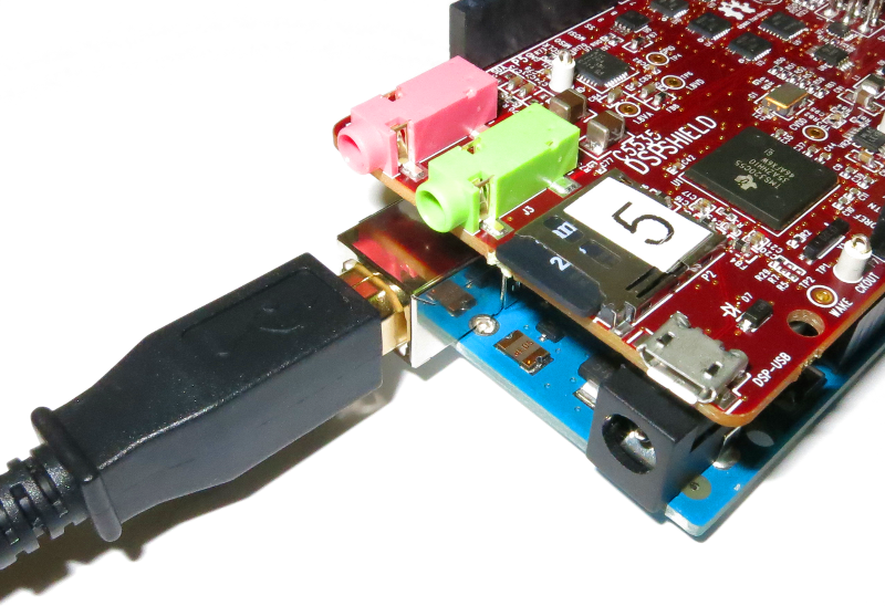
Figure 1: DSP Shield and Arduino.
The DSP Shield project is also a part of the larger “Lab In A Box” project which strives to bring the electronics lab out of university basements and make it into something that a student can toss in a bag and bring with them.
To this end, it is envisioned that the DSP will be used as a platform for developing all sorts of DSP based instruments. Teaching applications might include applications like filters or spectrum analyzers. Hobbyist applications like guitar pedals and vocoders may be realized as well. For the lab in a box project, instrumentation applications such as function generators, oscilloscopes, and network analyzers, can be developed to allow students to characterize and debug circuits that they construct without access to an expensive laboratory bench.
Questions about the DSP Shield, Lab-in-a-box project, or this page? Email me, William Esposito, at wespo@stanford.edu
Modes of Operation

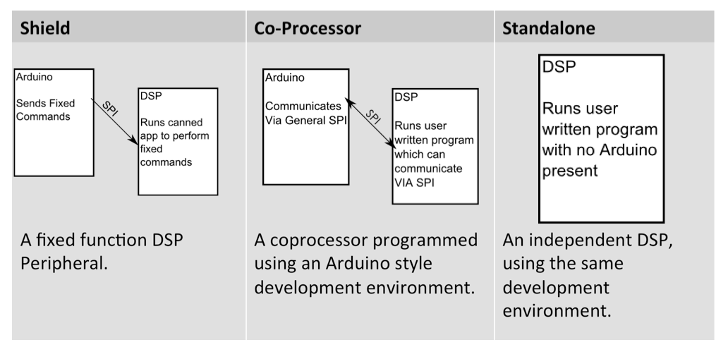
Figure 2: Chart showing DSP Shield modes.
The board is intended to be used in one of three primary modes:
- Simple “Shield” Mode.
A pre-programmed binary resides on the DSP Shield, which is physically stacked on top of the Arduino. The Arduino runs a library that can command the binary on the DSP to perform pre-determined signal processing applications (e.g. filter audio from the onboard audio codec with a provided list of coefficients). - Co-processor Mode.
The user writes their own DSP program using the Energia API, which is still physically stacked on top of the Arduino. The API uses Arduino style function calls and code, including a friendly signal processing library. The Arduino can communicate with the DSP via a pre-built high level messaging protocol. Code is uploaded via the Arduino’s USB port using the shared serial bus. - Standalone Mode
As a standalone DSP development board.The user writes code as before, but the Arduino is not present. The DSP is the sole processor and is programmed via its own micro-USB port. Energia can still be used, just as before, but Code Composer Studio can be used as well.
 Figure 3: DSP Shield in "Shield" or "Co-Processor" mode uses the USB port on the Arduino.
 Figure 4: DSP Shield in "Standalone" mode uses the USB port on the FTDI module, found near the OLED display.
DSP Shield as an Arduino Shield (Shield Mode)
As described above, the DSP Shield can be used as a conventional Arduino Shield in "Shield Mode". In this mode, the DSP Shield can be used to implement:
- Signal Generation
- FIR filtering
- IIR filtering
- FFT/Spectral Analysis

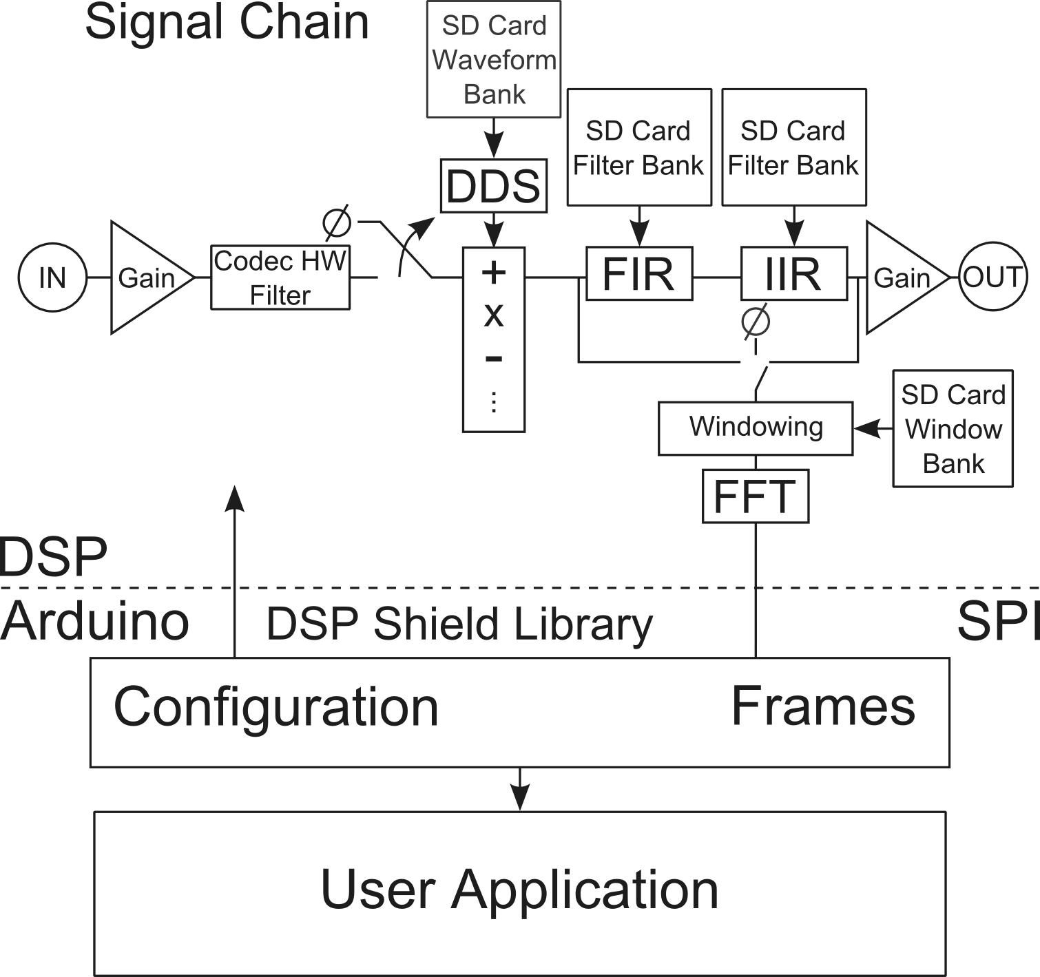
Figure 5: Block Diagram of Shield Mode Application Signal Chain (Image taken from "The Lab-in-a-box Project: An Arduino Compatible Signals And Electronics Teaching System").
In Shield Mode, the DSP Shield runs a pre-compiled application and the is controlled from a sketch running on an attached Arduino via the SPI bus and associated DSP Shield libraries. These libraries expose a group of pre-designed signal processing functions implemented by the Shield Mode Application.

Figure 6: Layers of DSP Shield Mode Stack (Image taken from "The Lab-in-a-box Project: An Arduino Compatible Signals And Electronics Teaching System").
To use the DSP Shield in shield mode, simply copy the 'bootimg.bin' file for the DSP-Shield-Mode Application into the root directory of the micro-SD card on the DSP Shield using a PC, then reset the DSP Shield. Once the application is running, it can be controlled via SPI from an Arduino using two libraries, the mailbox library and the DSP Shield Library. The manual for the DSP Shield library is included with the library but can be found here, as well.
DSP Shield Hardware Description
The DSP Shield is an Arduino Shield form factor single board DSP, based on the TI TMS320C5517 DSP Core, paired with a number of useful peripherals, including an SD card adapter, OLED display, Audio Codec, and I2C GPIO expanders that allow the DSP to mimic the Arduino’s GPIO headers.
 Figure 7: DSP Shield high level block diagram.
Below is a list of some of the key hardware on the DSP Shield board.
- TI TMS320C5517 (200MHz) Digital Signal Processor
- TI TLV320AIC3204IRGBR Stereo Audio Codec with separate stereo in and stereo out connectors, capable of sample rates of up to 96ksps
- Micro SD Card Connector
- USB 2.0 interface to the C5517 DSP
- OLED 96x16 pixel display
- Arduino Compatible Header Connectors
- Arduino Interface is compatible with Energia software IDE and API
- Embedded USB XDS100-V2 JTAG emulator with secondary serial port
- JTAG is compatible with TI Code Composer Studio software IDE
- Secondary serial port is compatible with Energia software IDE and API
- 40-pin DSP Expansion Connector
- 3 user controlled LEDs
- 4 user readable DIP switches
- 1 hardware reset push button switch
- Flexible Power Sourcing
Reference Documents
The full board hardware manual is available here:
DSP Shield Hardware Reference Manual R0.4 (References Previous C5535 Revsion of DSP Shield).
A higher resolution schematic is available here:
C5517 DSP Shield Schematic
Additional Hardware Documentation
For users who need additional detail about the DSP Shield hardware, here are a number of useful guides on the hardware used on the DSP Shield
-
Relevant Documentation for the DSP Shield:
- Datasheet for the DSP Shield's C5517 DSP core
- Datasheet for the DSP Shield's I2C GPIO Expanders
- Datasheet for the DSP Shield's Audio Codec
- User's Guide for the DSP Shield SPI Bus
- User's Guide for the DSP Shield I2C Bus Relevant document for the shield mode stack:
- Application note for using SPI on the Arduino Uno
Communicating With the DSP Shield
The DSP Shield has several ways of communicating off board (that is "with the outside world").
Serial (UART)
The DSP Shield has a Serial port that can be used to communicate with the PC, but which can be reconfigured for a number of uses including communicating with the Arduino. When the shield is programmed by Energia for standalone mode (described above), the serial port is connected to the USB port on the FTDI XDS-100 chip next to the OLED display. When the board is in shield mode, the DSP shares a Serial bus with the Arduino, and the serial output is visible on the same terminal as the Arduino stacked with the DSP Shield.
SPI
The DSP Shield has and SPI bus which is used to communicate with the Arduino. This can be programmed directly much like on Arduino, but can also be interfaced using the high level "Mailbox" library (available here) which allows for bidirectional communication with the Arduino. Unfortunately, the DSP Shield is only capable of acting as an SPI master, and the Arduino must be configured as an SPI slave on this bus.
I2C Bus and GPIO
The DSP Shield has an onboard I2C bus which it uses to communicate with onboard peripherals, including the GPIO expander chips which connect to the Arduino compatible headers. It is possible to connect the DSP Shield and Arduino I2C buses, allowing the Arduino to communicate with the DSP or to directly control any of the peripherals on the DSP Shield, including the Audio Codec and OLED Display. It is recommended that only experts actually connect these two I2C spaces.
Importantly, all users writing code for the DSP Shield itself (in Energia or Code Composer Studio) should take a moment to read the one page long App. Note DSP-01 on the behavior of the GPIO and I2C subsystems.
OLED Display
The DSP Shield's OLED display can be driven using high level print statements much like serial communication and can be used to send status information to the user.
Software Description and Downloads
As described above, the DSP shield will be made available with a precompiled binary that allows it to act as an Arduino shield and receive commands from the Arduino to active fixed function DSP blocks. The binary and source are available for download here. To compile this application, the DSP Mailbox library, found here is required. The necessary Arduino libraries to communicate with the DSP Shield are here and here.
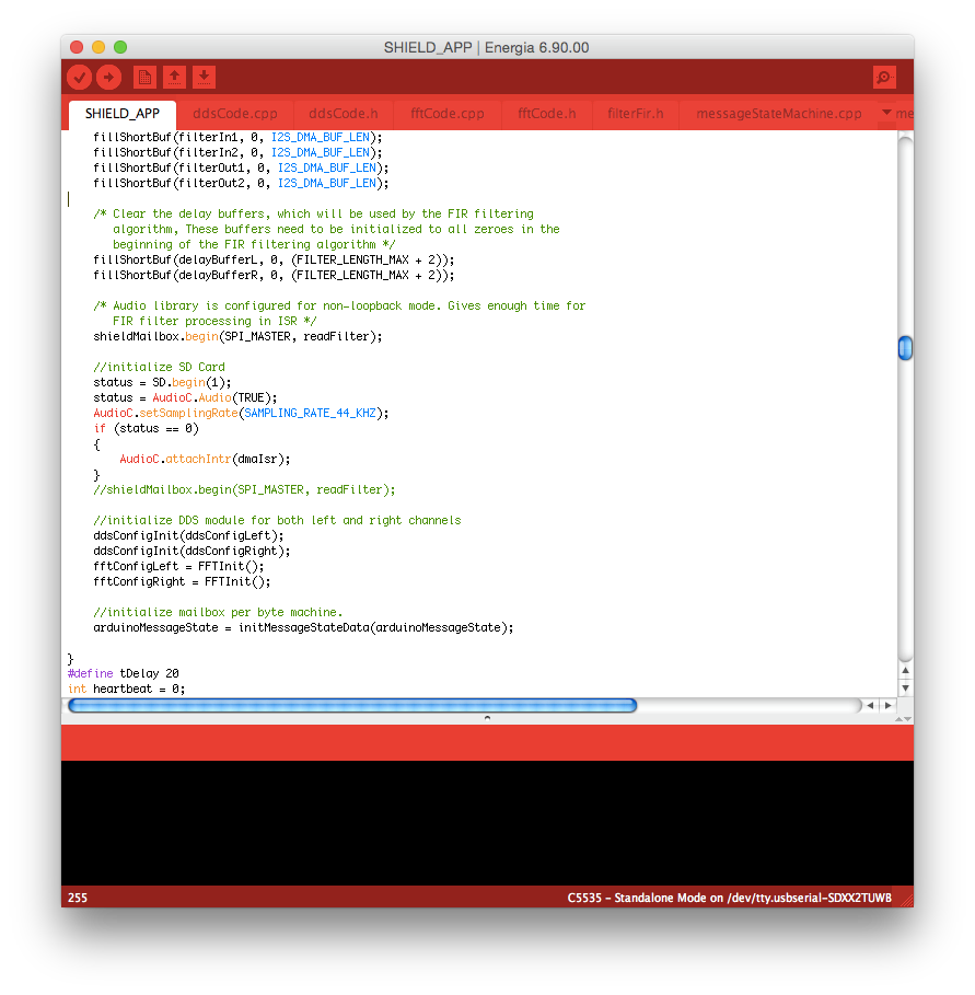
 Figure 8: DSP Shield software in Energia
For the Co-processor or Standalone modes, the DSP Shield itself is supported by Energia, an open source fork of Arduino focused on supporting Texas Instruments’ line of microcontrollers (and now DSPs). The current version of Energia on energia.nu does not support the DSP Shield. Support will be added to the main trunk before December 2014, and this page will be correspondingly updated.
A robust, Arduino-like interface has been developed for the DSP shield and it can be used to develop or teach a long list of DSP algorithms in a user-friendly way
Software Documentation
The DSP Shield API is designed to mimic as many of the familiar Arduino IDE conventions as possible. This means C++ style dot notation for hardware interfaces (AudioC.begin()), and standard function calls like "digitalWrite(pin)" and "digitalRead(pin)" (again, take note of App. Note DSP-01 which provides some advice on using the DSP Shield's onboard GPIO).
The full DSP Shield software reference manual has been generated via Doxygen thanks to comments added by Stanford student Maisy Wiseman, and can be found here:
DSP Shield API Reference Manual
Additional Software Documentation
The DSP Shield API in Energia was built incorporating a number of TI libraries and TI's compilers. Here is a partial list of documents for those tools. A user running the DSP Shield in shield mode should never need to reference these documents, and even most users of standalone mode are unlikely to need them, but they are good reference materials to have available.
- C5517 CPU Reference Guide. Describes C5517 memory space and available registers.
- C55x Compiler User's Guide. Details functionality of the C55x compilers used by Energia.
- DSP Shield Chip Support Library (CSL) reference guide. Covers hardware specific commands like GPIO, SD cards, etc.
Unfortunately, this document is for an older version of the CSL than used by the DSP Shield, and thus is only partially accurate. The current version of the CSL documentation is only available as part of the CSL download. - DSP Library User's Guide. Supports DSP functionality on vectors. Filtering and the like.
Programming The Board
The DSP Shield can be programmed via a serial bootloader much like a modern microcontroller. The user application is stored on the nonvolatile microSD card on the DSP shield, as the DSP core has no on chip flash memory. This also means that the DSP shield can be programmed indirectly by simply copying the binary generated by Energia onto the SD card using a PC – Energia itself will store a binary in the sketch directory when the verify or upload button is clicked (to compile the program).
Switching Between Standalone and Shield Mode

Figure 9: DSP Shield mode selection in Energia
App. Note DSP-02 describes how to convert the DSP Shield between "Shield" and "Standalone" modes, in order to allow use with or without an Arduino present. For "co-processor" mode, the Shield mode setup should be used.
Acknowledgements
This list will be far from complete, but I would like to take a moment to extend my thanks for continued support and encouragement to my advisor, Dr. Gregory Kovacs, as well as Dr. Fernando Mujica, Dr. Laurent Giovangrandi, Domingo Garcia, Cathy Wicks, Robert Wessels, Martin Izzard, and the entirety of Texas Instruments. Without the support of everyone involved, this project would not exist today.
