Spice Analysis of Single Buck Inverter


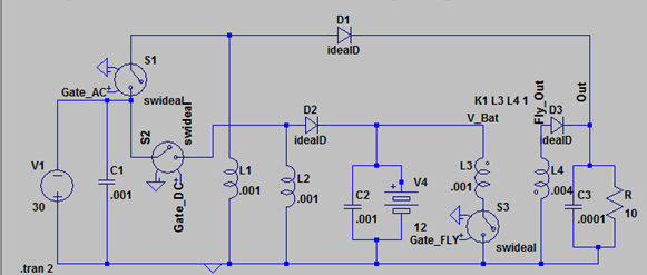
Our first step in testing our design was confirming the functionality of the two buck/boost inverters. Gate_AC is driven by PULSE V2 and when we PULSE this gate this with all other gates off we have a single buck/boost inverter. With a input voltage of 30V, a duty of 17/20 and ½ should produce 170V and 30V, respectively at the output, as shown here:

Testing AC Buck/Boost with D=0.85 or 17/20

Testing AC Buck/Boost with D=0.5
We are not concerned by the ripple at start-up because this SPICE does not test controls. The voltage settles to 30V as predicted.
Parallel Buck/Boosts
Next we wish to confirm that the two Buck/boost converters can work at the same time. The lead acid battery in our system (modeled in SPICE by a large capacitor) needs around 15V to charge. When the input voltage is 30 we need a duty of ⅓ applied to the Gate_DC in our circuit. Also, to reduce the fluctuation of the power drawn on the Cbig, the duty cycles of Gate_AC and Gate_DC will be offset by ½ the period.Gate pulses: note the start time for Gate_DC starting at 5us while Gate_AC starts at 0s

Gate pulses: note the start time for Gate_DC starting at 5us while Gate_AC starts at 0s
When we run the duty cycle at ⅓ we get the expected 15V output.

Gate_AC is boosting to 100V and Gate_DC is bucking to 15V

Current through our 10 Ohm load resistor (blue) and our battery (red)
The current through the battery fluctuates as predicted by the laws governing buck/boost converters with barely any fluctuation at all. If the current ever became negative during this test then our battery would discharge and charge at frequencies that would damage it.C

Current through the battery

Current through the output load resistor
Again we see the typical fluctuation of a buck/boost output current.
We will notice that the voltage and currents in these inductors are not exactly at their expected values and this is due to resistive losses in inductors, capacitors and semiconductive devices.
We will notice that the voltage and currents in these inductors are not exactly at their expected values and this is due to resistive losses in inductors, capacitors and semiconductive devices.
Flyback & Buck/Boost
Now we want to confirm that the flyback operates properly. To do this we must now treat the battery not as a capacitor but as a voltage source of 12V.
We must have the flyback and buck/boost voltage be the same at the output. Kirchoff’s law tells us that the currents will add and thus the power will sum up to the correct load power demand. We set both duty factors so that the voltages would equal 70V and the current would be 7A. In the following figure we see that result (note Amps on second y axis to right).

Output load current

Zoomed in output voltage across the load
If we increase the load resistance to 100 Ohms, we should see the current decrease to 0.7A.
