Overview
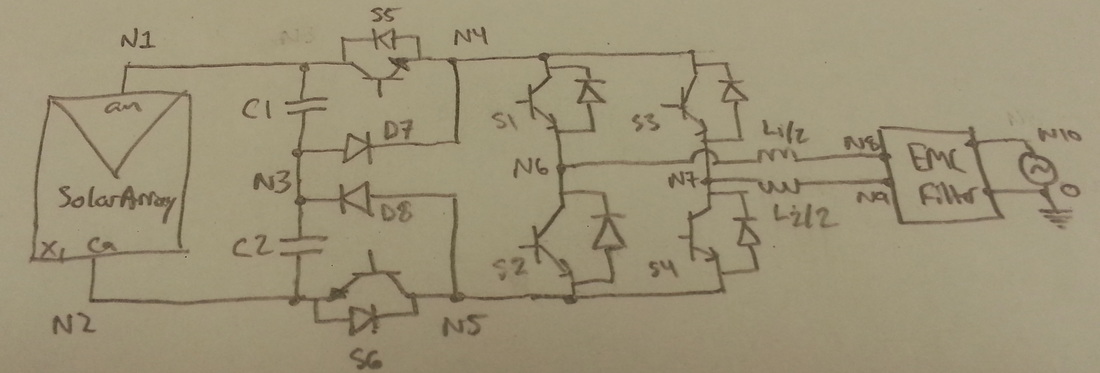
The transformerless inverter topology is composed of six switches and two diodes. In this topology, the diodes and the capacitors control the bypass voltage, while the switches S5 and S6 determine the blocked voltage. The bypass voltage is set to half the input voltage from the solar array. When S5 and S6 are on, the full voltage from the solar array (Vpv) is supplied to the full bridge stage. When S5 and S6 are off, the bypass voltage (Vpv/2) from the capacitors is supplied to the full bridge stage. The switches in the full bridge stage toggle in a particular fashion to help regulate the common mode voltage, which should be kept at Vpv/2 or (VN6 + VN7)/2 for the whole switching cycle. The voltage at these nodes can be seen by first looking at the positive half cycle. For the first stage of the positive half cycle, V(N6) = Vpv and V(N7) = 0V, yielding a common mode voltage of Vpv/2. In the second stage of this cycle V(N6) = V(N7) = Vpv/2, again yielding a common mode voltage of Vpv/2. This occurs similarly with the negative half cycle. Further analysis of the four commutation states of this topology is performed below.
Positive Half CycleS1 and S4 are on for both intervals.
Interval 1 S2 and S3 are off. S5 and S6 are on. N6 is at Vpv, N7 is at 0V. Interval 2 S2 and S3 are on. S5 and S6 are off. N6 and N7 are both at Vpv/2. |
Negative Half CycleS2 and S3 are on for both intervals.
Interval 3 S1 and S4 are off. S5 and S6 are on. N6 is at 0V, N7 is at Vpv. Interval 4 S1 and S4 are on. S5 and S6 are off. N6 and N7 are at Vpv/2. |