Shooter (unfinished)
Shafts
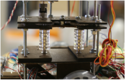
The primary aspect of the shooter mechanism lay in the two vertically-mounted 1/4" aluminum shafts, around which acrylic spokes ran. The shafts were mounted into the shooter base and top, attached at each point with small bearings sunken into the Duron. It was our intent to wrap foam, rubber bands, or some other high-friction material which would transmit the rotational velocity from the central shaft to the Nerf balls, forcing them along and eventually up the track. However, our team never successfully progressed the shooter to this point.
The primary aspect of the shooter mechanism lay in the two vertically-mounted 1/4" aluminum shafts, around which acrylic spokes ran. The shafts were mounted into the shooter base and top, attached at each point with small bearings sunken into the Duron. It was our intent to wrap foam, rubber bands, or some other high-friction material which would transmit the rotational velocity from the central shaft to the Nerf balls, forcing them along and eventually up the track. However, our team never successfully progressed the shooter to this point.

Gears
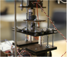
The beauty of the shooter mechanism lay in its unique gear structure. Rather than use two motors to power our primary shafts (one for each vertical column of acrylic and rubber), our team opted to use a single motor for the entire mechanism and connect the shafts via an overhead system of gears, which would be mounted axially with small 1/4" aluminum shafts and supported at either end, top and bottom, by small bearings sunken into 1/8" Duron sheets. The result was a sort of sandwiched effect, using two sizes (1" diameter and 1.25" diameter) of 1/4" thick acrylic gears to transmit both torque and rotational velocity from the motor mechanism to the shooting shafts. Our gears were very carefully designed, using methods certified by ASME and subscribing to standard measurement gear principles; each gear had a module of precisely 0.025" and either 20 or 25 teeth depending on the desired diameter. (See Note: Gears).
The beauty of the shooter mechanism lay in its unique gear structure. Rather than use two motors to power our primary shafts (one for each vertical column of acrylic and rubber), our team opted to use a single motor for the entire mechanism and connect the shafts via an overhead system of gears, which would be mounted axially with small 1/4" aluminum shafts and supported at either end, top and bottom, by small bearings sunken into 1/8" Duron sheets. The result was a sort of sandwiched effect, using two sizes (1" diameter and 1.25" diameter) of 1/4" thick acrylic gears to transmit both torque and rotational velocity from the motor mechanism to the shooting shafts. Our gears were very carefully designed, using methods certified by ASME and subscribing to standard measurement gear principles; each gear had a module of precisely 0.025" and either 20 or 25 teeth depending on the desired diameter. (See Note: Gears).
Layers
Though the robot itself was not designed in layers, the shooting mechanism was. It consisted of four main layers:
Though the robot itself was not designed in layers, the shooting mechanism was. It consisted of four main layers:
- A lower layer of 1/4" Duron, providing a mounting position for the entire mechanism
- A lower layer of 1/8" Duron, into which the base of the shafts was sunken.
- An upper layer of 1/8" Duron, into which the top of the shafts and the base of the gears was sunken
- A final upper layer of 1/8" Duron, which supported the top parts of the gear shafts and the motor braces