Stepper Motor

Driver/Circuit
The stepper motor was connected in a simple circuit to a Polulu DRV8825 Stepper Driver, shown right. This driver had the singular advantage of being bidirectional, which allowed the dunk arm to be both raised and lowered during the test run. Also, the max current it could sink was approximately 2.2 A per phase, a very significant number especially given the fact that a mechanical advantage already existed on the dunk arm (thus, we certainly did not lack for torque in operating this mechanism). Pins 8 and 9 from the Arduino Uno were used to operate this driver; pin 8 was the directional HIGH/LOW pin and pin 9 served as the PWM pin and varied the speed. The Mod 0, 1, and 2 pins on the driver were pulled low, driving the motor one full step per pulse, while the V_CC pin was directly connected to the 9.6-V power supply.
The stepper motor was connected in a simple circuit to a Polulu DRV8825 Stepper Driver, shown right. This driver had the singular advantage of being bidirectional, which allowed the dunk arm to be both raised and lowered during the test run. Also, the max current it could sink was approximately 2.2 A per phase, a very significant number especially given the fact that a mechanical advantage already existed on the dunk arm (thus, we certainly did not lack for torque in operating this mechanism). Pins 8 and 9 from the Arduino Uno were used to operate this driver; pin 8 was the directional HIGH/LOW pin and pin 9 served as the PWM pin and varied the speed. The Mod 0, 1, and 2 pins on the driver were pulled low, driving the motor one full step per pulse, while the V_CC pin was directly connected to the 9.6-V power supply.

Mount
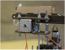
The stepper motor was mounted initially to two sheets of 1/4" Duron with corner braces, two on top and two on bottom. The sheets were again strengthened by running 5/16" threaded rods, bolted into place with metal nuts and washers on either side to ensure stability. Finally, a third rod (one of the four main support rods) ran through this mount and the dunk mechanism, adding a third level of stability and firmly mounting one to the other. The result was an incredibly stable mount.
The stepper motor was mounted initially to two sheets of 1/4" Duron with corner braces, two on top and two on bottom. The sheets were again strengthened by running 5/16" threaded rods, bolted into place with metal nuts and washers on either side to ensure stability. Finally, a third rod (one of the four main support rods) ran through this mount and the dunk mechanism, adding a third level of stability and firmly mounting one to the other. The result was an incredibly stable mount.
Create a free website
Start your own free website
A surprisingly easy drag & drop site creator. Learn more.

