Arduino
Arduino is an inexpensive, easy-to-use platform for small electronics projects, which has become extremely popular in the hobby electronics community. We'll be using an Arduino microcontroller board for the useless box, LED cube and electrocardiogram lab projects.
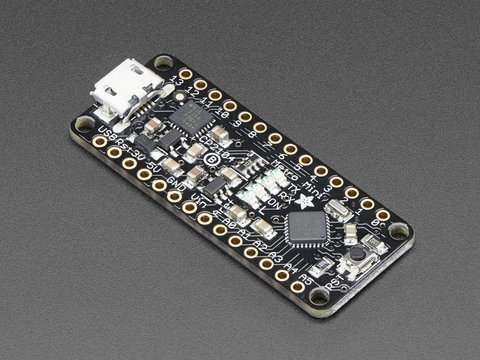
There are dozens of Arduino boards, of different sizes and capabilities. The one we're using is not technically an Arduino, but rather an Arduino-compatible derivative made by Adafruit known as the Metro Mini.
Setting up tools is an unavoidable part of making stuff, but we don't want getting the Arduino to work to be a time sink for anyone. So if you're encountering problems and you're not sure what to do, please ask so you can move on to the fun parts of lab!
Installing the Arduino IDE
Download the Arduino IDE appropriate for your system from the Arduino website, and install it. You're also welcome to try the web editor, but we make no guarantees that it will work.
For detailed instructions, see the Getting Started guides:
Mac users will additionally need to install the SiLabs drivers.
If you somehow have an older Metro Mini which has an FTDI chip, then you'll need the FTDI drivers instead.
Testing your installation + your Arduino
To test things, we'll load a simple standard program “Blink” on to the Arduino, and confirm that it runs.
Set the Arduino to use the Metro Mini: Tools Menu > Board > Arduino Uno The Metro Mini is a derivative of the Uno, which is why we're using this setting.
Set the port. For Windows users, this should be COMx, where x is some number. For Mac users, this will be devttyusbserial-xxxx, where xxxx may be some number. For Linux users, this will be devttyUSB0 or possibly devttyACM0".
Open the 'Blink’ program: File menu > Examples > 01. Basics > Blink.
In the new window that opens, click the 'upload’ button:

The little TX and RX lights should flash on your Arduino, and after a few seconds you should see the message “Done uploading” on the IDE. You're ready to start writing your own code!

If it didn't work, have a look through our troubleshooting guide below. If none of those help you, come to an office hour and we'll see what we can do, and extend the guide
Once you've loaded Blink, that should be enough to get you going! But for those who want to dig a little deeper, there are full “getting started” instructions on the Arduino website.
Troubleshooting installation
When I click upload, it tries for a while but says it has a “problem uploading to board.”
Check that you've set the board to Uno: Tools > Board > Arduino Uno.
Check that you've set the port correctly: Tools > Port. This can be confusing; you might have to try a few different ports to see which one matches. One way to determine which port it is, is to unplug the Arduino and see which one disappears, and plug it back in and see which one re-appears.
When I click upload, I get an “stk500_getsync() download” error.
Pins 0 and 1 on the board are used for programming the chip, so if you have them tied to 5V or ground or if they're heavily loaded (driving an LED), the programming signal will get borked.
Hardware: Putting your Arduino circuit together
Inserting it into your breadboard
You will notice that your Arduino board doesn't have any pins on it. This won't prevent it from operating, but will make it hard for it to connect to your breadboard. So to make your chip work with your breadboard, you will first need to solder pins (which are included) into your board. They gave you more pins than you need, so first use the wire cutters to cut off the extra pins, and then solder them to your board. Make sure that the pins are perpendicular to the board, otherwise it will be hard to insert them into your breadboards.
If you ever need to take an Arduino out of a breadboard, don't be tempted to pull out one end, then the other! This can bend the pins into awkward positions. Either wriggle it out very gently, or use an IC extractor tool (the things that look like oversized useless tweezers in the lab).
Putting your circuit together
When your USB cable is connected, the 5V pin provides a 5 V source that you can use to power the rest of your circuit. Don't forget to connect everything that needs to be connected to ground, to GND. More details on this are in “Power pins” below.
The inputs from and outputs to the rest of your circuit connect to the input/output pins, taking into account their capabilities as described in “Input/output (I/O) pins” below.
Which pins do what?
All of this information is taken from the Arduino Nano specifications page.
Power pins
There are three ways to power the Arduino board.
When you plug in a USB cable, the Arduino will be powered from the USB cable. No other power source is necessary. In this case, VIN should be left unused. The 5V pin will be powered by the USB cable, and you can use this as a 5 V source for the rest of your circuit.
You can supply a constant 5 V directly to the 5V pin yourself (e.g., using the power supply on the lab benches). In this case, VIN should be left unused.
You can supply a voltage between 6 V and 20 V to the VIN pin. You probably won't be doing this. There is a voltage regulator chip on the board that will use this to generate a 5 V supply. The 5V pin will be powered by this, and you can use it as a 5 V source for the rest of the circuit.
When using your AA battery pack, which gives about 4.5 V, to power your Arduino board, you should connect it to the 5V pin. Then, just be aware that your circuit will be powered by 4.5 V, not 5V. Never do this at the same time as connecting a USB cable, because that will try to push the USB's 5 V on to your non-rechargeable 4.5 V batteries.
The VIN circuit is only capable of stepping down, not up, so connecting 4.5 V to VIN won't work. Also, the 3V3 pin doesn't power the Arduino, it's actually just a 3.3 V output that is generated when the USB cable is plugged in.
Input/output (I/O) pins
Pins RX0, TX1, and D2 through D13 are digital input/output pins. We often refer to these as just “pin 0” through “pin 13”, respectively.
Pins A0 through A5 can be used either as analog input or digital input/output (but not at the same time).
Pins A6 and A7 are analog input pins. They cannot be used as digital pins.
What about analog output? There's no true analog output on the Arduino microcontroller, but there are pins that support pulse-width modulation (PWM), which is close enough for our purposes. In something of a misnomer, this is controlled using the analogWrite() function. The (digital) I/O pins capable of this are 3, 5, 6, 9, 10 and 11.
Take note: All digital input/output pins can be configured as digital inputs or outputs. However, the analog input pins are not the same as the analog output pins!
Other pins
RST is the reset pin. When it is driven low (by you, e.g. if you connect it to GND), it resets the Arduino. You probably won't be using this. Note that the button on the board connects RST to GND when pressed, i.e. it is a reset button.
REF is an external reference for the analog input pins. You probably won't be using this. The “analog reference” is the voltage that configures the top of the analog input range, i.e what voltage would read 1023. By default, the reference is the 5 V supply, but if you want to use some other range, you can connect a voltage to this pin and configure the Arduino to use it with analogReference().
Software: Your own Arduino program
Often, it's most helpful to look at example programs to understand how they do things, and take snippets or modify them to do what you want to do. The examples (sometimes called “tutorials”) are in File > Examples, and there are helpful descriptions of them on in the Examples page on the Arduino website.
To get started, look at the ones in Basics, Analog and Digital. You can start to look at the others as you want to use more advanced functionality.
The basic structure of an Arduino program
Your basic Arduino template will look like this:
void setup() {
  // put your setup code here, to run once:

}

void loop() {
  // put your main code here, to run repeatedly:

}
The setup() function runs once when the Arduino is powered on. You should use this to configure pins (pinMode()) and, if you want to use the Serial Monitor, to run Serial.begin().
The loop() function runs repeatedly forever. You can think of it as being inside an infinite loop. In this loop, you read inputs and write to outputs, to achieve the effect you want on the rest of your circuit.
When you're programming a computer (in your CS courses), infinite loops are a bad thing to be avoided like the plague. In electronics, infinite loops aren't only acceptable, but necessary: your program is always monitoring inputs and adjusting outputs, which can only do if it's in an infinite loop.
The Arduino reference
Once you're in the swing of programming, you might want to keep the Arduino language reference handy. It has a complete guide to much more than you need to know about the Arduino, so you certainly don't need to be familiar with it, but if you're wondering how a function works or whether there's a function to do what you want, it's a great guide.