Lab 5: Car Key Fobs
Overview
For the next part of the course we will look at a digital signals. These encoded digital information using the analog signals we have been studying so far. This week we will start with the key fob for your car. These have been getting a lot of attention recently, and with good reason!
Aims of the Lab
The goal of the lab is to capture and understand how key fobs work.
Your Car's Remote
Most cars use a Remote Keyless System (RKS). When you push the button on the remote, it sends a signal to the car, and it opens the door.
You can capture your car's remote signal with your RTLSDR. These are usually around 315 MHz +/- 2.5 MHz. Here is capture for my Prius key
This was sampled at 2.048 MHz and includes 10 seconds of data. There are two key presses in the file. This is a nice simple example to get us started.
To capture signals from your key fob, first you need to figure out what frequency it transmits on. Connect your SDR and use GQRX or SDR# to monitor the spectrum. When you push a button on the fob, you should see a brief jump in the spectrum. It isn't subtle, and should be very obvious. Capture a screen shot if you can, it will be useful later. You may need to shift the frequency band up or down by a couple of MHz to find the signal, my Prius was almost 2.5 MHz low.
One word of caution. Don't get too carried away pushing the button! The RKS system uses a rolling pseudo-randomly generated code. Both the key fob and the car keep in sync, so that the car recognizes the next code. However, if the key fob gets too far ahead in the sequence (100s of button pushes) the car won't recognize it. That makes the key (and the car) considerably less useful! This can take a trip to the dealership to fix.
First we need to find where the signals are. We can find them by plotting the magnitude of the signal
>> load('rke312590.mat');               # data is in variable dt
>> t = [1:length(dt])/2048000;              # Time for sampling rate of 2.048 MHz
>> plot(t(1:1000:end),abs(dt(1:1000:end)));
where we skipping by 1000 samples to keep the plot size manageable. The result is shown below
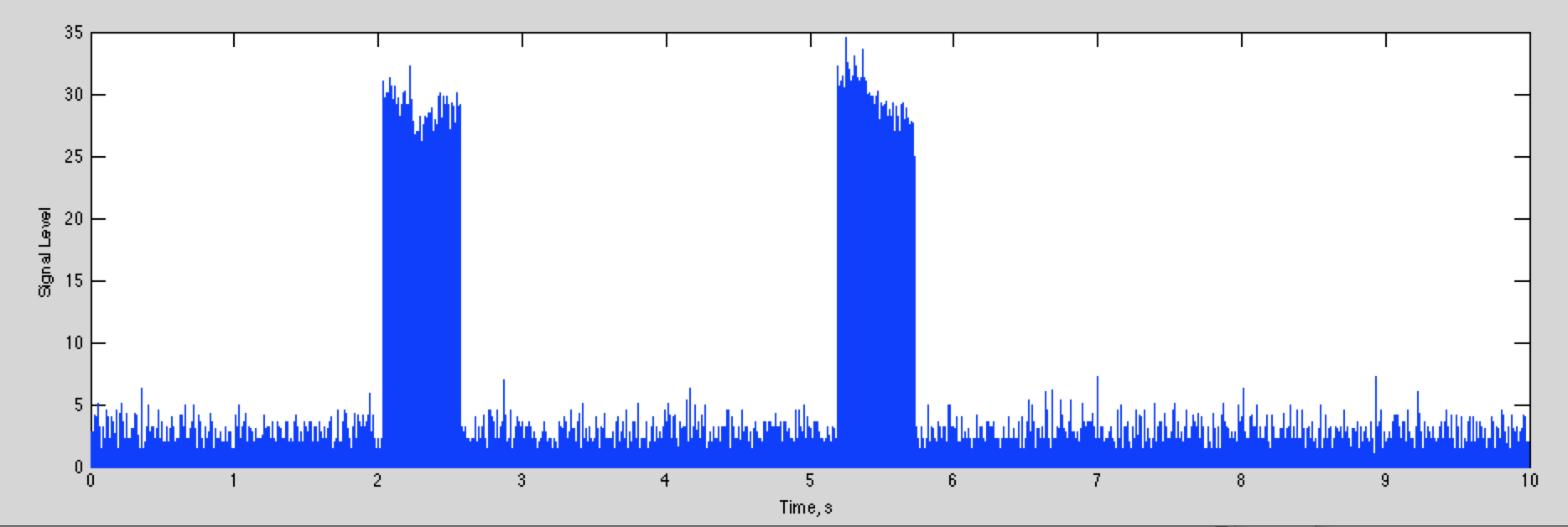
The total width of the plot is 10 seconds, so you can see there is one key press shortly after 2 seconds, and another shortly after 5 seconds.
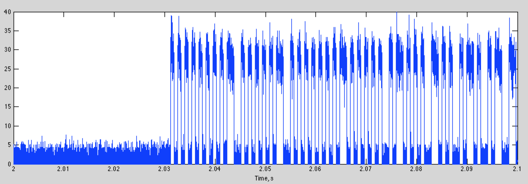
If we plot 100 ms starting at 2 seconds, we can see the digital signal we are looking for:
which looks like this
Zooming in to the first couple of bits, we get
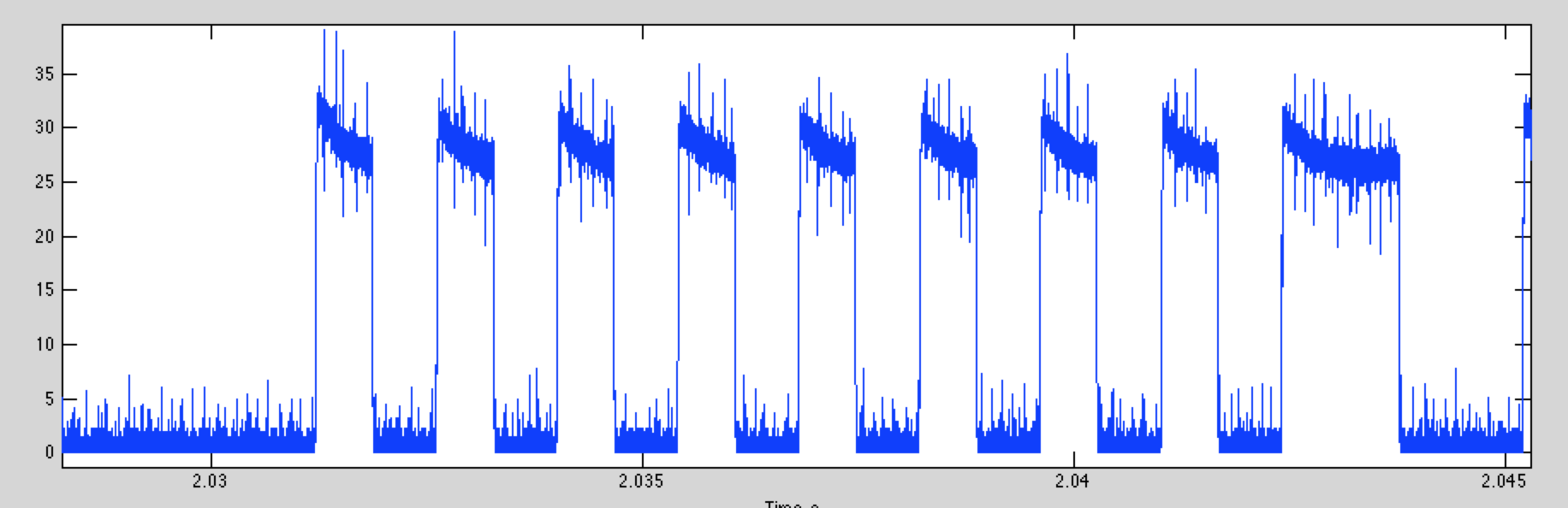
The bits are easy to identify. A decision threshold of 15 will give almost perfect detection (your data will have a different level)
If we do this, and then plot first part of the digital data for the two key presses, we get this
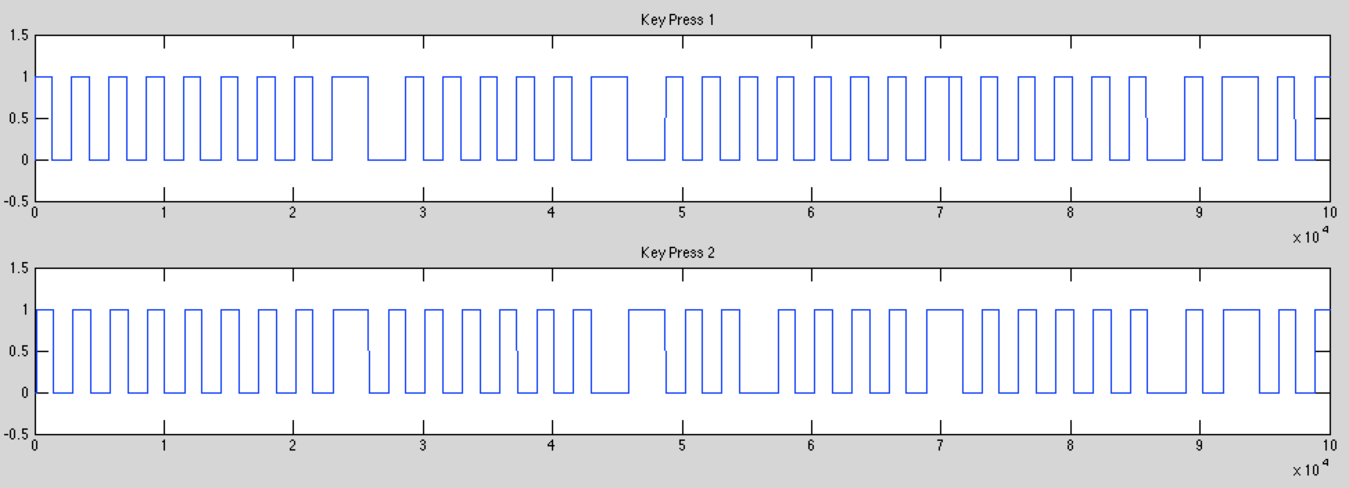
Although the two start the same, they rapidly diverge. This is fortunate, because if the signal was the same every time, you'd have enough information to steal my car now!
This is a simple on-off-keying signal (OOK). It is also almost certainly split phase (or Manchester) encoding. Instead of a "1" being high, and a "0" being low, the information is encoding in the transition from high to low or low to high. That means that a "0" bit is a rising transition, and a "1" bit is a falling transition. A good way to recognize split phase encoding is that you can only have one or two low or high segments in a row. The nice thing about Manchester encoding is that every symbol has a transition, and these are easier to find then when the signal has been high or low for several intervals. We will talk about this next week.
While OOK is common for car remotes, as we'll see in the Lab, there are other encoding schemes used. These include Frequency Shift Keying (FSK), where different frequencies represent the different bits, and Phase Shift Keying (PSK) where the phase of the carrier encodes the different bits.
Attacks on Car Remotes
There are lots of different attacks that can be used against car remotes, depending on how they work, and what sort of access you are looking for. The simplest just let you open the car up. More thorough attacks give you complete control by basically cloning the remote.
Most key fobs use a rolling key. This produces a new waveform that depends on the ID of the key fob, a random seed, and how many times the key has been pressed. The car keeps track of the last code it received, and knows what the next several hundred codes might be. If it detects one of the expected future codes it opens the car. If it gets a previously used code, it stops responding to the key fob. For the Prius you have to do the "Chicken Dance" to get it to work again, provided you have another working key fob. Otherwise, you have to have the dealer rekey the car, for many hundreds of dollars. I have had to do this a couple times, now (for other reasons).
There are several lines of attack. One is simply recording the key fob output for a couple of button presses when it is away from the car, or the car is being jammed. With recorded unused codes, you can open the car.
Another is to reverse engineer the RKS sequence. In general this should be extremely hard. However, there have been several situations where this is very easy.
Finally, there are cars that open when the owner gets close to the car. This is based on a low power signal that can only be received when the key fob is very close. This can be defeated by amplifying these small signals.
There are many more attacks, and these will continue to multiply as cars get more complex, and have more embedded computer systems to go after.
Replay Attacks
The oldest and simplest approach was to record the waveform that a key fob puts out (using your rtl-sdr), and then replay it. This works well for older garage door openers, that used a single fixed key. There are still cars out there that have key fobs that work this way (some pre-2000 Mercedes for example).
For key fobs that use a rolling key, you can still use a replay attack. If you can get access to the key fob when it is away from the car and record several key presses, you can replay these to have the car open.
If you can't get access to the key fob, a second approach is to make a device that records the output of the key fob when it is used, and simultaneously jams the car. A standard way to do this is to listen to the key fob transmission, and then start jamming when the error correction bits are transmitted at the end. That way you don't jam yourself. The car won't recognize the packet, but you can recreate the error correction bits, and retransmit the waveform later.
Finally, a jammer by itself will keep the remote from begin able to lock the car. If the driver isn't attentive, they may walk away from the car leaving it open.
Retransmission Devices
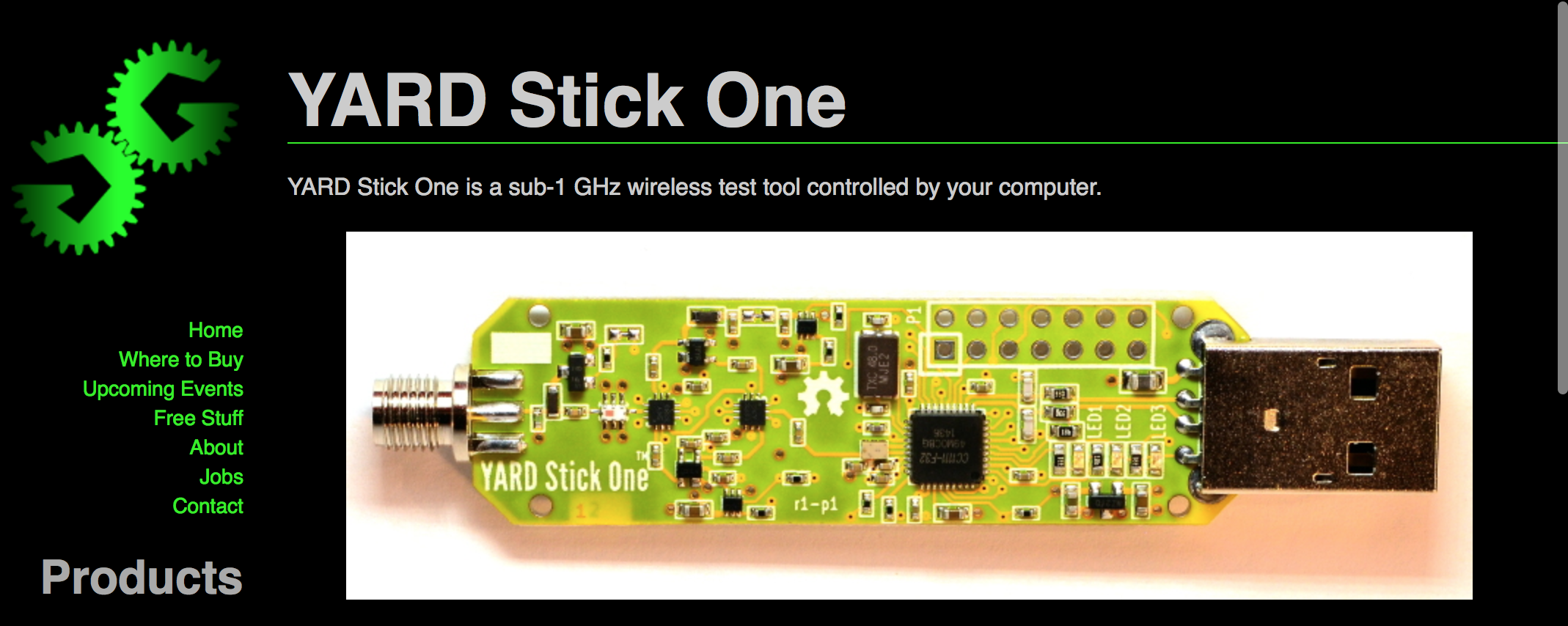
All of this depends on your ability to both transmit and receive RF. Your rtl-sdr's are just receivers, and do a great job of acquiring signals. There are lots of options for transmitting. There are a number of usb dongles that are based on the TI CC111X chips that are used in key fobs, like this one
A more recent package that does this using basically the same hardware is the Flipper Zero
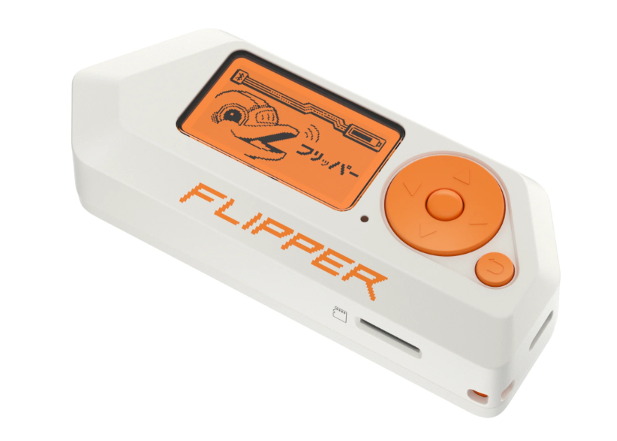
These have the same chip as your key fob, but also have a nice user interface, and is preprogrammed to deal with all sorts of interesting devices, like key cards, wireless car remotes, bluetooth devices, and chips for your pet. For car remotes this can perform replay attacks, but that is about it. It can't perform rolling key attacks, or relay attacks (at least right now). Interestingly, there is a proposal in Canada to ban these devices. Maybe that will happen here! So get yours now while you can.
Fundamentally banning devices like the Flipper Zero is a pointless exercise. None of this is hard to do. An interesting, very flexible approach uses your Raspberry PI to generate RF by sending a carefully crafted data sequence to the GPIO port. This is described in detail, with videos, and links to the code here:
With this, you can generate pretty much any digital packet waveform you would like. Power levels are more than adequate for emulating a key fob. The rtl-sdr's are also well supported on the Raspberry PI, so the two together give you a total key fob hacking system for $50 or so, as we will see shortly.
Attacking Passive Keyless Entry and Start (PKES) Systems
Many higher end cars use a passive system for opening the car when the driver approaches. A low power signal is transmitted from the car as a challenge. The key fob then responds with an authentication. Because the power is so low, the car assumes the driver must be in close proximity if it receives a response.
These systems can be hacked by building a repeater that placed near the car. It captures the car's signal and retransmits it at higher power. The remote can be anywhere with in a couple hundred meters, and it will still hear the signal. The remote responds, and that is again captured by the repeater, and retransmitted. The car thinks the key fob is nearby and opens the car.
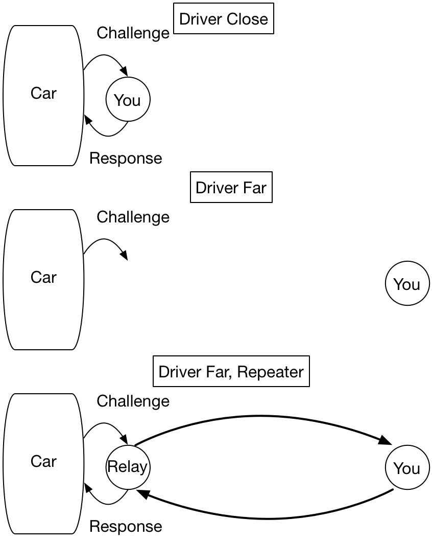
The nice thing about this approach is that you don't need to know anything about the key fob, except its frequency. You don't need to reverse engineer the protocol it uses, you are actually just using the real key!
Here is a video of some care thieves stealing a Tesla with this approach
Passive Remote Attack, Tesla Model 3
How can you reduce this risk?
Attacking the Rolling Key System
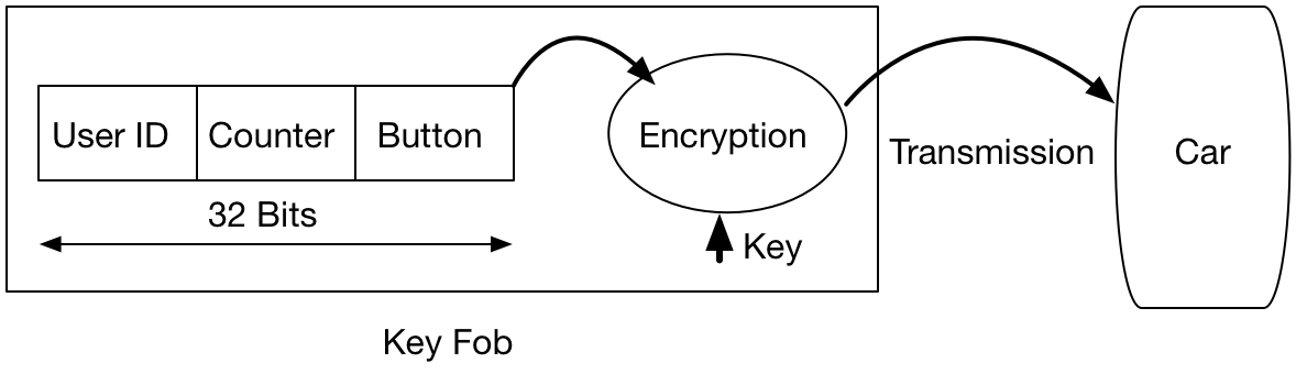
The next attacks go after the rolling key system itself. The way this generally works is that the key fob sends an ID, along with a counter of how many times a key has been pressed. This is encrypted, and transmitted to the car when you push the button.
If the encryption is strong, it is extremely difficult to figure out what the userid and counter is. There are several interesting cases. One is for the 20 years of VW's (and Audi's, Porsche's, etc).
A description of the VW RKS system is given here
This points to a Wired article (which unfortunately currently behind a paywall), and includes a technical paper that goes into great detail about how it works. The authors of the technical paper looked at the VW RKS systems for the last 20 years.
For the most recent systems, the encryption was relatively strong, equivalent to a 90 bit key. However, it turns out they used the same key in every car! 100 million of them!
The challenge then is to figure out what the key is, and what the encryption algorithm is. The car itself helps you solve that one. When button is pushed the car receives the signal, and then decodes it in the onboard computer (ECU). The key and the algorithm are stored in the ECU firmware. The authors bought some ECUs on EBay, downloaded the firmware, and reverse engineered the encryption (these are usually fairly simple bitwise operations that are easy to identify). With this knowledge, after acquiring the signal from a single key press, the user ID and counter can be decoded, and the key fob cloned, giving complete control of the car.
There are a couple of interesting things here. One is that every VW car decodes every key fob, so by monitoring the execution of your ECU, you can find the user ID and counter for all of the cars around you. There are reports of people using systems like this to steal other makes of cars, also.
The reason only your car responds to your remote is that your car has a "allow list" of key fob ID's it responds to. That is what gets set when you rekey the car.
Another very interesing case is for Subarus. This article concerns the Subaru RKS system.
Here the algorithm they used to generate the next pseudo-random key is "+1". Basically, if you can eavesdrop on one button press, you can generate as many keys as you'd like. The article includes a YouTube video demonstrating how this works in real life.
Lab Report
For your lab report, we'll look at a couple of other key fob signals. I've captured a couple here:
These were sampled at 2.4 MHz, and were trimmed down in length to just include the key press. The acquisition parameters are included in the file. The data is in the variables dp, da, and dm for the Prius, Audi, and Mazda, respectively.
You can also use the signal from your own keyfob. If it is OOK encoded, use it for the first part, and if it isn't, use it for the second part.
1. The Audi Signal
This is OOK. Assume that one bit is a transition from high to low, or low to high. Each bit takes two pulses. This is Manchester encoding, which we will talk about next class.
- Plot the waveform and describe what you see.
- How long is one bit in time for the Audi?
- How many bits are in the signal?
Approximate answers are fine.
2. The Mazda Signal
The Mazda uses a different encoding scheme that is more common for newer cars. Your task is to figure out how the bits are encoded. The following process works for the Mazda keyfob. Your key fob may be different, and you may have to adapt this process to figure out what it is doing
a) Time Signal
Decimate the signal down to 240 kHz sampling rate (a factor of 10) and plot the amplitude of the signal.
>> load('mazda_key.mat');
>> dmd = decimate(dm,10);       % decimate to +/- 120 kHz, or 240 kHz sampling rate
>> fsa = fs / 10;           % fs is 2.4e6, included int he mat file
>> t = [1:length(dmd)]/fsa      % Time in seconds
>> plot(t,abs(dmd));
>> xlabel('Time, s')
>> ylabel('Amplitude')
Zoom in to the plot and describe what you see. Is this OOK? Include the plot with your report.
b) Plot the Spectrogram
Plot the spectrogram of the signal. Using blocks of 240 samples means that one sample in frequency is one kHz. This will make estimating the frequency easier.
Describe what you see. Include your spectrogram in your report.
c) Decode the Signal
The signal uses two frequencies 96 kHz apart, which you can estimate from the spectrogram. This is frequency shift keying (FSK). A "1" is sent with one frequency, and a "0" with the other.
The easiest way to decode the signal is to just extract the signal for one of the bits. You can do this by
- Finding the offset frequency of one of the peaks. It doesn't have to be too accurate.
- Demodulate that peak to baseband (i.e zero frequency, or the middle of the spectrogram). Check with the spectrogram to see that it is now centered.
- Decimate the signal by a factor of 6, so that your sampling rate is now 40 kHz. This will eliminate the other frequency.
- Plot the absolute value of the signal
At this point it should look like an OOK signal.
For your report,
- Include a plot of the absolute value of the entire signal,
- A zoomed in section of the first half,
- and a zoomed in section of the second half.
For zooming in, it is helpful to zoom only in the time (or x) direction. use
>> zoom xon  % zoom in the x axis only
:
:  % your plotting stuff here
:
>> zoom off % return to default state
What is the purpose of the first half? What would happen if you decoded the other frequency?
At this point we could extract the sequence of bits for the entire signal. However, this isn't that interesting. We'll go on to this next week when there is something human readable to decode.